Operation of S-Series Cameras
S-series cameras use triangulation with a laser pattern for generating 3D data. This is different from the stereo matching approach that our other models use and thus requires some differences in the API.
Note
The API of S-series cameras is currently in a beta state and might change slightly in the future. Please read the comments below to make your usage of the current API as future-proof as possible.
Laser Projector Heating
Structured light cameras require a constant temperature of the laser diode. The device contains a heater which is used to adjust the temperature to a fixed value automatically.
As soon as the device is plugged in it will start to pre-heat the laser to a fixed temperature below the normal operating temperature. This can take several minutes when the device was at room temperature before. When the device is opened in the NxLib it will heat the laser to the normal operating temperature, which can take a few additional seconds.
Before using the data from an S-series camera you should check that laser heating is finished and the laser temperature is in the expected range by using the ProjectorTemperatureReached flag. When the laser temperature is not in the expected range, stereo matching can fail or produce incorrect data.
Camera Node
In general, the camera node of an S-series camera is very similar to the camera node of a stereo camera. The most important difference is that a structured light camera has only one image. Its Images node therefore looks more like a mono camera.
The Parameters node is also very similar to the one of a stereo camera except for the stereo matching parameters. You can find some details on those in the next sections.
Computing 3D Data
A structured light camera does not have a disparity map, it only has the PointMap. For technical reasons, this point map is currently computed by the ComputeDisparityMap command. The ComputePointMap command does nothing for structured light cameras.
This might change in the future. We recommend to execute both the ComputeDisparityMap and ComputePointMap for now, which will always be a supported combination of commands to compute the point map.
Structured light cameras will return one data point for each point in the laser pattern. Since these points are quite sparse, S-series cameras enable the Downsample parameter by default. The resulting point map will therefore have a different resolution than the rectified sensor image. Note that the distance of points in the point map also has an effect on the 3D data filtering described in the next section.
Note
Computation of the point cloud is not deterministic. Recomputing the point cloud can change the data slightly even if no images or parameters changed.
Stereo Matching Parameters and Filtering 3D Data
S-series cameras do not have any parameters that influence stereo matching with the laser pattern. They only support some parameters for filtering the 3D data in a postprocessing step. Most of these are similar to the filters available for stereo cameras.
Note that the speckle removal filter for structured light cameras works differently than for stereo cameras. See the description of its parameters for details.
The window radius for median filter and speckle removal apply to the downsampled point map, not the original resolution of the sensor.
Note that for technical reasons the camera node of structured light cameras currently contains most of the stereo matching parameters that only apply to stereo cameras. These do not affect the 3D data of S-series cameras and will be removed in the future.
Functional Limitations
CUDA is currently not supported for structured light cameras. The ComputeDisparityMap command will match structured light cameras on the CPU regardless of the CUDA parameter.
Unmatched Regions in S-Series Images
The following image shows a part of an S-series camera image with the point map data overlayed. The colored pixels indicate the presence of 3D data. There are different regions in this images, where 3D points can or cannot be computed for different reasons.
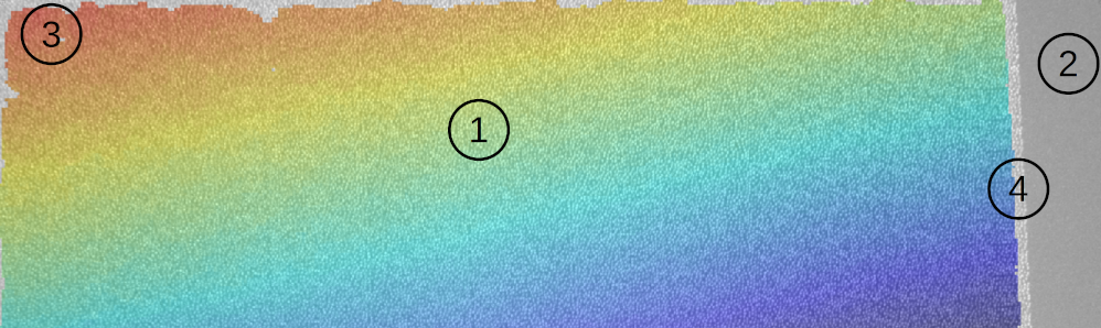
All points can be matched in the middle of the image.
The laser projector is not visible in this area due to the different viewing angles of camera and projector. The width of this area changes depending on the distance of the observed objects from the camera.
Matching laser points needs information from a window around the point. Laser points at the borders of the captured image area contain too few neighboring laser points in their window and cannot be matched.
Laser points at the border of the laser projector pattern can never have enough neighboring points in their window, regardless of the captured image area. They can never be matched. This region is similar to region 3, but is usually slightly larger.