Method
The method to use for stereo matching.
Format
String |
“Correlation” |
Use correlation-based stereo matching. |
“SgmAligned” |
Use Semi-Global-Matching with axis-aligned propagation. |
|
“SgmDiagonal” |
Use Semi-Global-Matching with diagonal propagation. |
|
“SgmAlignedAndDiagonal” |
Use Semi-Global-Matching with both axis-aligned and diagonal propagation. |
|
“SgmSinglePass” |
Use Semi-Global-Matching with propagation from top to bottom. |
|
“PatchMatch” |
Uses a variant of the PatchMatch algorithm |
Default
XR30 |
“SgmSinglePass” |
XR36 |
“Correlation” |
others |
“PatchMatch” |
Semi-Global Matching
For Semi-Global Matching (SGM), the method specifies the type of optimization that is carried out on the cost function.
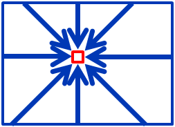
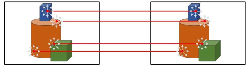
You can imagine that SGM propagates information about good stereo matches over the image in different directions. As an example, the image on the right uses 8 optimization directions. At each pixel, we use information from these 8 directions to find the best disparity value for this pixel. For more information about SGM, please see the research paper Hirschmüller, 2005: Accurate and efficient stereo processing by semi-global matching and mutual information.
“SgmAligned” propagates the cost along 4 paths that correspond to the pixel axes of the rectified images.
“SgmDiagonal” propagates the cost along 4 paths that correspond to all 45 degree pixel diagonals.
“SgmAlignedAndDiagonal” propagates the cost along 8 paths, both axis-aligned and diagonal. This setting yields the best matching results, but also has the slowest performance.
“SgmSinglePass” propagates the cost along 4 paths from left to right, top to bottom and the two downwards diagonals.
Profiles with less propagation directions will be faster, but might have problems with edges that are approximately aligned with one of the propagation directions.
Note
The “SgmAligned” and “SgmDiagonal” profiles have similar runtime, but object edges that are approximately aligned with one of the propagation directions might be estimated less accurately. You might for example choose the “SgmDiagonal” profile, if you expect you object edges to be mostly pixel axis aligned and “SgmAligned” for best results on non-pixel aligned object boundaries.
Note
The “SgmSinglePass” variant of SGM ist used on XR-series cameras. For other cameras, it is also implemented on CPU for testing purposes, but you should prefer one of the other SGM methods. This variant is not implemented in CUDA.
Sequence Correlation Stereo Matching
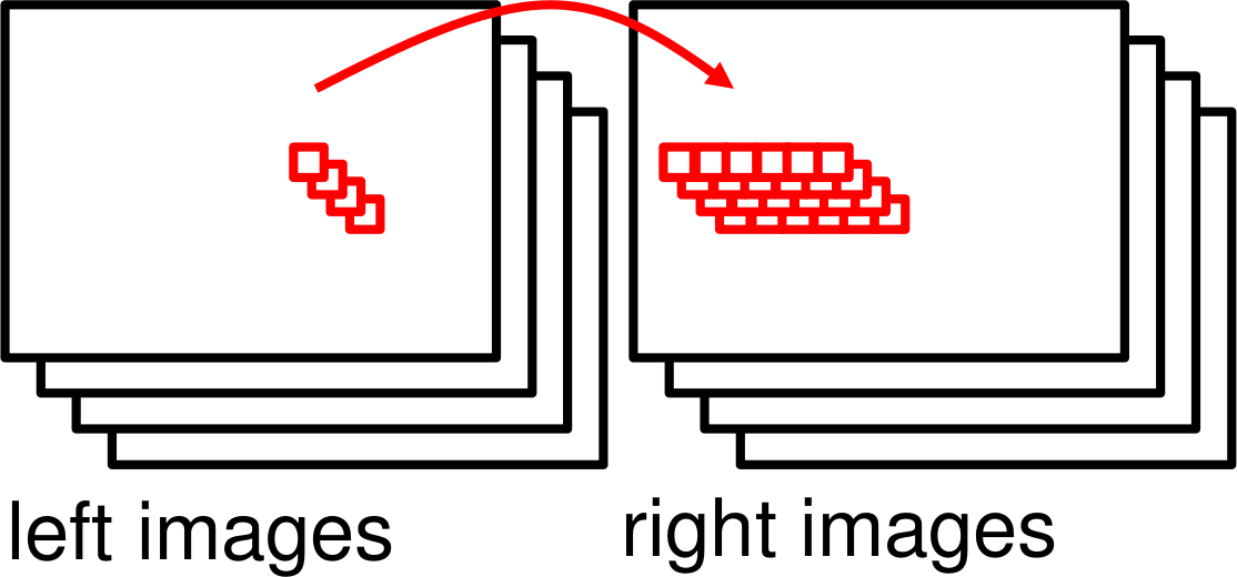
This method uses multiple images produced by cameras with FlexView. It finds the disparity for a pixel in the left image by correlating the corresponding pixel sequence (i.e. the same pixel across the different images) with all pixel sequences in the disparity range in the right image. The best disparity is the one where the pixel sequences have the highest correlation.
This method often has better accuracy and can resolve smaller details than Semi-Global Matching, but it needs at least 8 image pairs.
Note
In order to use correlation-based stereo matching, you need to enable FlexView and take at least 5 image pairs. Otherwise it will default to “SgmAlignedAndDiagonal”. Matching with fewer image pairs is possible when enabling the window radius parameter.
Using the correlation-based matching with window radius or multi-exposure factor is not supported on XR-series cameras.
PatchMatch Stereo Matching
PatchMatch is a randomized algorithm for finding correspondences between image patches. The matching procedure can be outlined as follows:
The matching starts by sampling random correspondences, i.e. we fill the disparity map with random values:
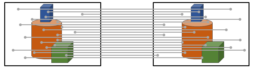
A certain percentage of these correspondences will be close to correct:
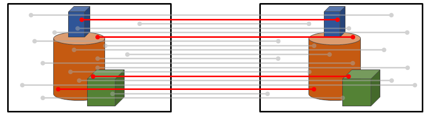
Then we try to propagate these correct samples to their still incorrect neighbors:
The propagation of disparity values is done iteratively in multiple directions. The local intensity differences between an image patch around each pixel provides the measure to distinguish between good and bad samples. Good samples can spread out over worse samples, but a bad sample will not propagate to a better associated neighbor pixel and the neighbors disparity value which yields a lower local patch difference will be kept instead.
The procedure fills the disparity map with a high percentage of correctly associated pixels even after the first iteration, i.e. propagating the values in all directions once. To improve the probability to hit small, disconnected surface patches it is possible to add more iterations using the Iterations parameter.
Stereo Matching Parameters
When using a matching method other than PatchMatch you need to preselect the desired measurement range, either manually, or by automatically guessing a suitable range. Please refer to the images below on how to accomplish this in NxView.
Click the A Button above the depth image view to automatically guess the depth range.
If auto adjustment of measurement range doesn’t produce suitable results go to the properties dialog and adjust the measurement range manually
When using one of the Semi-Global Matching variants you should choose a suitable value for the Depth Change Cost parameter.
Higher change cost results in less visible Z-noise, but can degrade the reproduction of steeply slanted surfaces in the depth data.
Lower change cost produces better Z-linearity in subpixel interpolation and deals better with steep surfaces while producing visibly more noise.