Joint configuration of the robot. This parameter is needed when robot poses are given as joint angles in the Angle parameter, instead of cartesian poses in the Transformations parameter.
Robot model
In order to compute Cartesian poses from the given joint angles NxLib needs to know the geometry of your robot. The robot model consist of a chain of transformations. Some transformations are fixed and correspond to a robot link (e.g. a part of the arm). In between the fixed links the model should have some actuated rotatory joints which are represented as identity transformations. These identity transformations should have a rotation axis specified corresponding to the actual axis direction of the actuated joint. The calibration procedure will then fill in the rotation angles from the Angle parameter into the rotation angles of the identity transformations in the robot model to obtain a Cartesian robot pose (forward kinematics).
Example
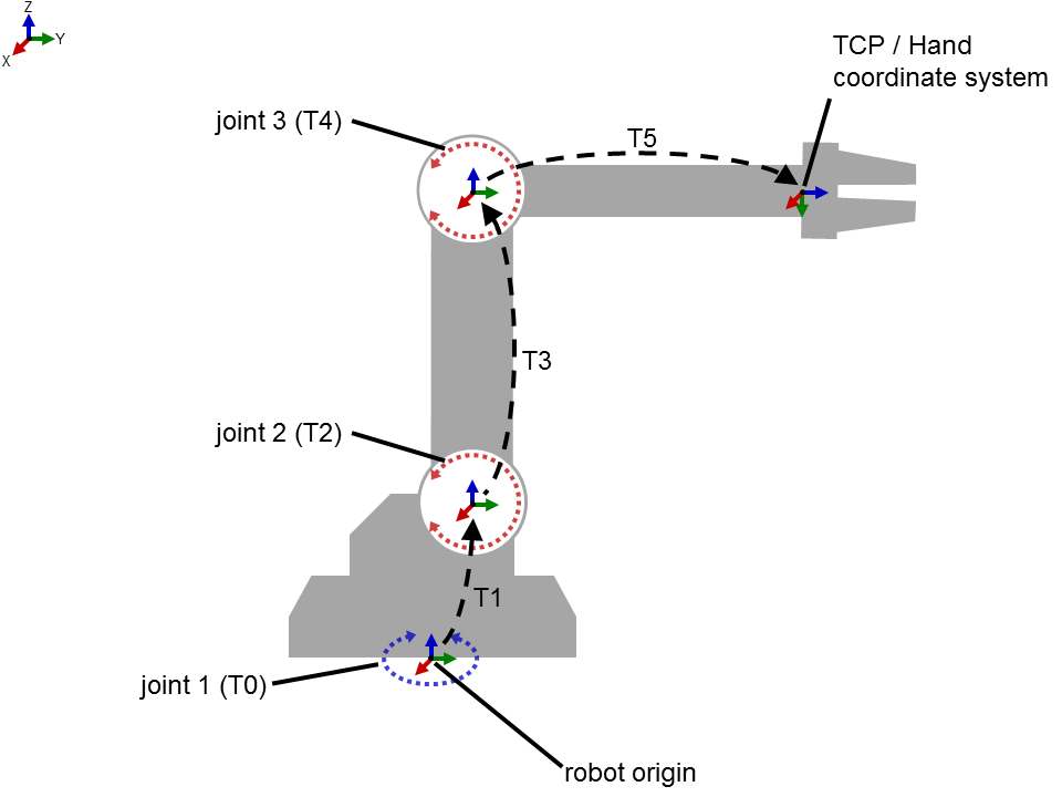
Let's assume you have the simple robot as shown below. It has only 3 rotational joints and 3 static parts. The link tree describing the robot and its joints in its zero position consists of the following transformation chain in JSON format:
[
|
Note: Omitting the Rotation or Translation items will simply be interpreted as a transformation having no Rotation or Translation respectively.
Each identity transformation in the link tree having a non-zero rotation axis and angle 0 and translation [0,0,0] will be interpreted as an actuated rotational joint of the robot. The hand-eye calibration will internally insert the joint angles from the Angle parameter of each pose into the Angle part of the detected joint transformations to obtain the Cartesian robot poses by forward kinematics.
Note: The transformation T5 could have been written as a single transformation containing both Rotation and Translation, but has been broken up into separate parts for clarity.
The resulting robot poses will be obtained by chaining the transformations in the order as given in the link tree, e.g. the robot pose (e.g. the TCP in the robot origin) for the first pattern is computed as:
Pose0 = T0(J10) • T1 • T2(J20) • T3 • T4(J30) • T5
Where the subscript indices indicate the index of a pattern observation and the corresponding robot pose. J10 to J30 are the robot joint angles for observation 0 in our example; your robot will likely have more than 3 axes.
Consistency Checking
When the Transformations and Angle parameters are given, the command performs a consistency check: it verifies that the joint angles in the Angle parameter together with the robot model from the Links parameter yield the same positions and orientations as the corresponding pose in the Transformations parameter. Currently the checking tolerances are fixed to 1 mm in translation and 1 degree in rotation. If any pose violates this consistency check the command fails and outputs the observed pose difference.
