SpeckleRemoval
Speckle filtering is usually needed in areas where surfaces are outside the matching range. In these regions, stereo matching will usually produce very small, incorrectly triangulated patches. This is due to ambiguous texture which cannot be associated correctly between the left and right camera, if the specified disparity depth range prevents the search in the correctly matching areas. The subnodes of this node allow to control the removal of such speckle regions.
Format
Object |
A parameter sub tree. Please refer to the description of the sub nodes for further information. |
Note
The speckle filter uses different parameters for stereo cameras and structured light cameras.
Working Principle for Stereo Cameras
For stereo cameras, speckle filtering is performed in two passes:
Separate disparity map into regions. A region ends at invalid pixels, or at depth discontinuities larger than ComponentThreshold, specified in disparities.
Remove regions whose area (measured in pixels) is smaller than RegionSize. Pixels of removed regions will be set to invalid.
Note
Setting RegionSize to 0 disables the speckle filter.
Example
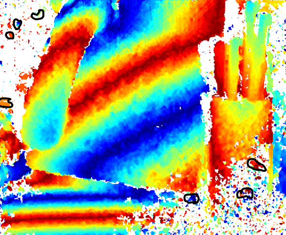
Depth image without speckle filter. Some regions as they may result from step (1) are marked in black:
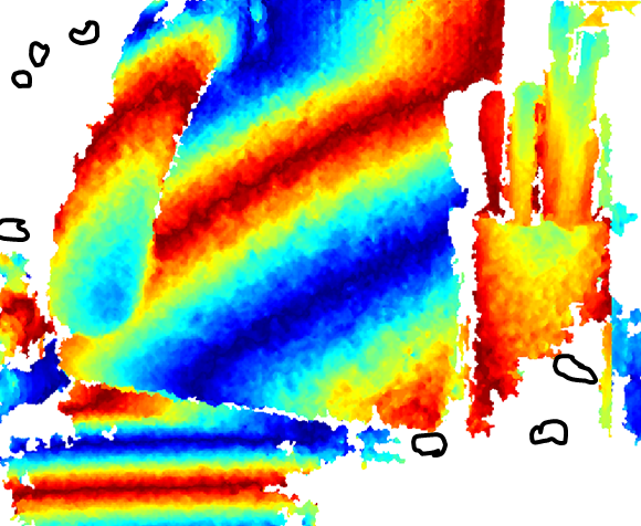
Depth image with speckle filter applied. Small, detached regions have been removed, as well as some larger areas that have been cut into multiple regions by step (1).
Working Principle for Structured Light Cameras
For structured light cameras, the speckle filter counts how many of the points in a window around any given point lie within the ComponentThreshold. The MinimumPointRatio parameter specifies the ratio of points that must be at a similar depth in order for the test to pass. The size of the window is controlled by the WindowRadius parameter.
Note
Setting WindowRadius to 0 disables the speckle filter.